Figure 1 Logical versus physical data flow in the ISO model.
Linux IP Stacks Commentary Web Edition
Linux And The ISO Model
Table of Contents
Layer 6 — The Presentation Layer
Layer 7 — The Application Layer
The section background traced the evolution of TCP/IP and explained how, under the aegis of the Defense Advanced Research Projects Agency (DARPA), it grew from a protocol for a single network into a protocol that could link many networks. Thanks to the solution provided by TCP/IP, the ARPAnet grew from a single network into a collective network that led eventually to today’s Internet.
However, long before DARPA’s practical-minded engineers were busy devising a system that would let hundreds of university research departments and defense contractors swap information on a day-to-day basis, groups of theoreticians were equally busy building conceptual models for computer networking in general. Such models would give networking researchers and implementers a way to discuss their work without getting bogged down in proprietary details: in other words, it would provide a common design metalanguage that would stay valid until the arrival of the next paradigm-shifting breakthrough in communications theory (which, at this writing, we’re still awaiting).
As it turned out, the networking world’s answer to the Grand Unified Field Theory was actually unveiled long before TCP/IP had gelled as the practical choice for internetworked communications. Proving that concepts can travel faster than electrons, the International Organization for Standardization (ISO) introduced its model in 1974, while formal work on TCP/IP was still in its early days. In fact, considering that work on TCP/IP continued for another decade (it wasn’t codified by the DOD as a U. S. federal standard until 1985, and is still being refined), we can safely assume that ISO’s theoretical model actually had some effect on DARPA’s practical method.
ISO, a federation of individual national standards agencies, was formally established in 1947, and is now based in Geneva, Switzerland.
The name “ISO” is not an orthographically impaired abbreviation of “International Organization for Standardization.” Instead, it’s a neologism derived from the Greek “isos” (“equal”), which is the root of many words, such as “isometric” (“of equal measure or dimensions”) and “isonomy” (“equality of laws,” or “equality of people before the law”). In ISO’s own words, “from ‘equal’ to ‘standard,’ the line of thinking that led to the choice of ‘ISO’… is easy to follow.” The use of “ISO” worldwide also avoids the host of abbreviations derived from the translation of the organization’s name into the languages of its 130-odd member nations. Whatever the country, the name stays the same.
In a move destined to confuse future generations of computer communications neophytes, ISO named its brainchild the “Open Systems Interconnection (OSI) model.” Although it owed much to existing mainframe-based networks, including in particular the System Network Architecture (SNA) developed by IBM, the OSI model was defined in a non-vendor-specific way. And, many of its principles jibed surprising well, up to a point, with DARPA’s minicomputer-based, TCP/IP-linked systems. More later.
ISO’s purpose in creating the OSI model was not only to provide a design metalanguage, as previously mentioned, but also to define standards for protocols that fit within the model. Unhappily for ISO, the OSI protocol definitions proved to be less than useful in the commercial world, which is why not much is heard about this aspect of the model today.
So, you may be wondering why we are bothering with the ISO/OSI model at all? Because, as the model’s designers foresaw, a well-known benchmark not only gives network researchers and implementers a common language, but also makes improvements easier to integrate into existing systems. The OSI model is studied in every college-level course on computer networking, and every article on networking issues uses the model as a basis for discussion — despite the fact that when the time comes to implement a protocol built to fit the OSI model, the model turns out to be cumbersome, at best.
However, a flawed model is not necessarily useless. The model of the atom developed by Niels Bohr still has its uses in chemistry today, even though the quantum model is “better” at making accurate predictions about what “real” matter will do. But, not every chemist is always in the prediction business, and for most chemists’ purposes, the Bohr model is still perfectly useful. In the same way, the ISO/OSI networking model is still a fine tool — in fact, the best tool we have — for understanding what all the various bits and pieces of any given network protocol are doing.
If you’re already familiar with the ISO/OSI model, this chapter will give you a good overview of how TCP/IP fits into this standard framework; skip to the subsection “Mapping TCP/IP To The OSI Model”.
If you’re a TCP/IP guru, the following discussion will provide a bridge between your intimate knowledge of the Internet and the contents of technical articles in the published literature. If you’re new to networking, you’ll find that the ISO/OSI model offers a divide-and-conquer approach that reduces the networking “elephant” to more easily digestible “byte-sized” pieces.
The fundamental difference between the OSI model and TCP/IP: the former imposes rigid separations between networking functions, whereas TCP/IP does not. This isn’t to say that there is no compartmentalization of functions in TCP/IP; simply that, in order to reduce computational overhead and thereby improve its performance, TCP/IP takes a less doctrinaire approach to this issue than the OSI model does. One particular TCP/IP implementation that is much more efficient than the OSI model is, of course, the Linux implementation.
As you’ll soon see, the original ISO/OSI networking model discussed in this chapter does not include any paradigms for connectionless communications. These issues have been addressed by addendums to the model that have been incorporated over the years. However, because these addendums can be confusing, the following discussion sticks with the original model and deals with the exceptions separately.
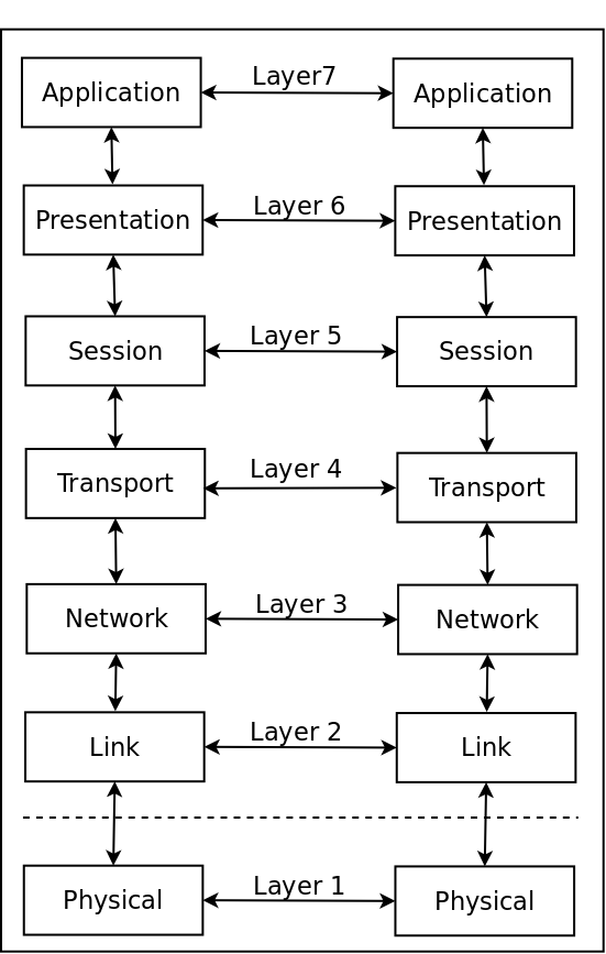
The ISO/OSI networking model consists of seven layers of functions, arranged for convenience in the form of a vertical stack. The functions closest to the physical user live at the top of the stack, while the functions located closest to the communications hardware live at the bottom. When two computers are communicating, the software in each layer in one computer “talks” with the software in the corresponding layer in the other computer. Communications between any two corresponding layers always use the services performed by the lower layers in each stack, as shown in Figure 3.1.
Figure
1 Logical versus physical data flow in the ISO model.
The solid line connecting the boxes marked “Physical” is the only physical connection between the computers (with the understanding that this “physical” connection may also be infrared or wireless). The arrows and dotted lines linking the other six levels, which are all implemented in software, show the logical data path.
Imagine two colleagues, each of whom works in an office located high at the top of neighboring skyscraper buildings in New York City. To seal a deal with a personal handshake, one of them must travel down to ground level, walk across the street level to the other building, and ride up through all the intervening floors to his colleague’s office. This route is exactly analogous to the pathway followed by the information sent by one network user to another, with the data traveling down the ISO stack to the physical layer in the first user’s system, across to the physical layer in the second user’s system, and up to the top of the ISO stack in that system.
The detailed descriptions of the layers in the OSI stack will be easier to understand if you have a conceptual framework to fit them into. You can start at the top of the stack, with user applications, not only because of their familiarity, but also because they contain all the functions and entities that live on the lower layers.
The applications that live on Layer 7 can be anything from order-entry systems or airline-reservations systems to library reference-information databases or museum catalog-exchange systems, to name just a few common examples. In terms of their OSI stack function, the applications define the data sets that are transferred and manipulated by the software on Layers 6 through 2. The data sets consist of information, arranged in a format defined by the application, that is updated and examined over time.
With the data sets defined, you can step down to Layer 6, whose job is to ensure that the data can be interpreted properly by each type of system (hardware and OS) connected to the network. That’s why Layer 6 is called the presentation layer. It deals with differences in the binary representation of floating-point operations, and also with code-conversion issues involving ASCII, Extended Binary Coded Decimal Interchange Code (EBCDIC), Unicode, and special alphabet equivalencies. As you’ll see later in this section, these responsibilities have recently been expanded to include encryption management.
Layer 5, the session layer, determines how each group of interactions between two or more computer systems is handled. Such a group of interactions might consist of, for example, the steps that have to be performed so that an order can be properly placed and tracked in an order-entry system.
Layer 5 is supported by Layer 4, the transport layer, which is responsible for ensuring that individual transactions are completed reliably. For example, in an order-entry application, an individual transaction might consist of issuing a notice about the availability of a particular item. Layer 4 is supposed to make sure that the notice is transported reliably from one system to another. If it can’t do the job, Layer 4 must report its failure to the entity that requested the transaction.
Layer 3, the network layer, provides the data-transfer switching function that allows the messages sent by Layer 4 to reach the system they’re supposed to reach. Mind you, Layer 3 doesn’t actually make sure the messages reach their destination. Any number of bad things can keep that from happening. But, without the directions provided, traffic-cop style, by Layer 3, the messages have no chance of getting anywhere at all.
Layer 2, the link layer, oversees the transfer of messages between its own system and a neighboring, physically connected system. Of course, the neighboring system need not be the message’s ultimate addressee; it could be just the first of many way-stations en route to the final destination. Layer 2 “oversees” because, although it makes sure that an outgoing message is launched, it can’t ensure that the message reaches its destination. Layer 2’s other job is to capture incoming messages. However (as described later in this section), Layer 2 doesn’t take any steps to confirm either the accuracy of those messages or their freedom from errors.
At the bottom of the stack is the only non-software layer. Layer 1 deals with the actual physical transmission of data — electrically, optically, radioly, or even (if the system uses conceptual carrier pigeons as described in RFC 1149 and 2549) ornithologically.
For convenience, in the following discussion, the term “message” refers to the individual elements of a conversation between systems. When humans converse, one person says something, and the other person replies. The “something” is an idea or thought, and a complete unit of meaning conveyed is a “message.” Most networking protocols work exactly the same way. So, in the remainder of this chapter, the one-way transfer of discrete ideas or thoughts is referred to as a message, with a conversation between two computers consisting of exchanges of messages. Assume, for example, that your computer wants to learn the Internet address of the machine www.linux.org . To do so, it engages in a series of message exchanges with DNS name servers. The upshot of these message exchanges is that your computer is either told the address or informed that the address can’t be found. This type of conversation also takes place when an FTP client system is receiving a file from an FTP server. The server sends data in a message, and the client says “OK, I’ve got it; send me some more,” and so on, until the server says “There, you’ve got it all.”
Now, take a closer look at each layer in the stack, from the bottom up.
The “street level” of the OSI stack is the physical layer, which handles the nuts-and-bolts business of passing bits between two computers. This layer contains the hardware, and sometimes some of the driver software, components that deal with the transmission and reception of digital bits or groups of bits, such as bytes or groups of bytes — up to, but usually not including, complete messages.
The physical layer also performs low-level conversions. In this area, it can convert an electron-based digital bitstream to analog signaling (as in a modem, ISDN terminal adapter, microwave transmission system, wireless link, or satellite link) or to light-based signaling (in fiber-optic or infrared transmission systems).
As noted earlier in this chapter, the OSI model isolates its functions with the zeal of a boarding-school proctor guarding her charges on a field trip. Nowhere is this isolation more evident than in the partition between the physical layer (the only hardware layer) and the link layer (the first of the six software layers). In practice, however, the isolation is breaking down, thanks to certain innovative devices. Some Ethernet chipsets are now so smart that the interface between the physical layer and higher layers is on the chips themselves, and not in the computer at all.
The link layer is the first of the six software layers in the OSI stack. It handles the mechanics of launching messages over a physical connection to a neighboring computer, and of capturing messages that are received over the same physical connection, from the neighboring computer. In the OSI model, the link layer does not have to guarantee the correct transfer of data. (Dealing with dropped or incorrect data is the job of the upper-layer software.) Nor does the connection path that the link layer uses have to be bidirectional: for instance, it may be a part of a ring system. Ideally, though, the network of pathways should let each local computer talk to every other local computer, one way or another.
Even though the link layer isn’t required to transfer data reliably, implementations of link–level functionality are permitted to provide a degree of error control. In satellite links, for example, the transmission path is so long, and the likelihood of errors is so great, that some systems implement forward error correction. In this process, redundant data is added to the physical datastream so that errors can be caught (and, in many cases, corrected) at the receiving end with no further interaction. In practice, this capability can save significant amounts of expensive satellite-link time, because it can take as long as several seconds for a system to respond to a data-retransmission request issued at a higher level in the model. Closer to home, many modem links between individual computers and ISPs use International Telecommunications Union (ITU) Recommendation V.42 error control. The intent isn’t primarily to obtain an error-free link, but rather to allow the use of data compression, as described in ITU Recommendation V.42 bis, to increase the capacity of the link. In this respect, reliability is a byproduct of the data-compression scheme.
Although link-layer protocols are supposed to deal with pairs of directly (physically) connected computers, some link-layer protocols allow connections among three or more computers over the same network. The most common of these multiple-endpoint systems is Ethernet, followed closely by Token Ring networking. The OSI model treats each pair of endpoints on a shared network as a separate link-layer connection. In other words, a connection with n computers will have a maximum of n*(n-1) logical links.
The network layer, which gave the Internet its name, is responsible for routing packets over multiple links on a single network and through gateways between two or more networks. If changes need to be made in packets of information so that the packets can travel across networks, those changes (such as changing that data in the header, or splitting packets to fit the capacity of the transmission path) are made here. In short, this layer’s job is specifically to ensure that the data “gets through” the network(s). Any changes in the form of the data (such as character-set transformation or byte-order conversion) are the responsibility of the presentation layer, described later.
The network layer is where the message routing function lives. Whereas the routing function in a single host computer is straightforward, in a router, it is quite complex. So much so, in fact, that several very thick books have been written on the sole subject of routing over the Internet. Because we’re not writing one of those books, our discussion of routing is limited to how it works in conjunction with Linux on desktop computers that are connected to the Internet.
We’d say that routing is the “rocket science” of the Internet, but that wouldn’t be fair to rocket science, which is well-grounded and actually extremely rational (if not always intuitive). The “science” of routing is more analogous to the voodoo science of, say, economics— not least of which reasons is that they both offer arenas for the practical application of chaos theory and statistical analysis.
In short, the goal of Layer 3 is to take a message from an end-point computer and deliver it (if possible, intact) to the designated end-point computer, regardless of where the originating and receiving computers are located, and regardless of the Byzantine path the message may have to follow.
The transport layer is responsible for providing end-to-end connectivity between two specific computers on the network. This connectivity may consist of a stream of data, or may be in the form of a single “connectionless” exchange of messages. The transport layer is the lowest layer in which the only peer entities involved are the peers that live in the source and destination computers, and not in any of the way-station systems used by Layer 3 to transfer messages over the network.
Consider the implications of that last statement. The implementation of the bottom two layers (Layer 1 and Layer 2) communicates on a point-to-point basis, computer to computer. The network layer (Layer 3) knits multiple point-to-point links into a path, through one or many networks. The data stays at the network layer (or lower) until it reaches the destination computer. Only then does it travel to a higher layer in the OSI stack model. (Think of an underground pipeline, or a lawn-sprinkler conduit, that doesn’t surface until it gets to the specified endpoint.)
What about your multi-computer LAN? Can it be thought of as a point-to-point connection? Conceptually, yes. A LAN provides a logical point-to-point connection between pairs of machines, using a shared medium, and the LAN hardware functions in much the same way as the switch in a telephone system. Even though your voice call (network message) is handled by a potentially huge number of nodes, it appears to you that a direct private link exists between you (the source computer) and your interlocutor (the destination computer).
The protocols in the transport layer also have to worry about the Quality of Service (QoS) they provide to upper layers. The “Quality of Service” specification provides a handy way to characterize the most important aspects of data-transfer operations. The exact services that are needed may be different for each upper layer and for each Layer 7 application. For some applications, such as real-time audio, the timely arrival of data is more important than whether the data is error-free. For other applications, such as databases, accuracy and the proper sequencing of updates are far more important than the time it takes to complete a transaction. File transfers often occupy a middle ground: The error rate should be low and the connection should be robust, but the priority of the transfer is lower than that of a transfer of voice or music in real time. Or, a file transfer may have been instructed to use the cheapest path rather than the fastest one. The following list summarizes (in alphabetical order) the QoS metrics that may or may not be important to specific types of data transactions over the network:
The transport layer is the layer that’s usually most concerned with the correction of transmission errors, because the error rate is a QoS issue. The actual error-correction scheme that the transport layer employs is also dictated by the QoS requested by the upper layers. Sometimes, the transport layer simply has to indicate the presence of an error; other times, it has to “fix” the error, using whatever means it can find.
In a large network, such as the Internet, the transport layer is responsible for ensuring that, for streaming circuits, the data packets are presented to the upper layers on the receiving side in the same order in which they were presented to the transport layer on the sending side by the software residing on the upper layers. This is because when routing messages, some parts of messages will take one path, other parts another path, and so arrive “backwards” at the destination computer.
The session layer defines the format of the data that will be transmitted over the transport layer’s connection, and also specifies the way in which the data will be exchanged.
A good example of a session-layer protocol is the Remote Procedure Call (RPC) protocol, as defined originally in the Xerox Network System (XNS) and replicated in several other networking systems (including the TCP/IP implementation of Linux). This protocol extends the concept of a function or subroutine call to a multiple-machine environment, allowing a program residing on one system to call a function or a subroutine residing on another system. The client-session protocol (the caller) makes a call to a remote procedure and passes parameters. The server-session protocol (the responder) then performs the remote procedure, returning a response to the call. Sun’s Network File System (NFS) implementation uses RPCs to gain access to remote file systems, with each RPC performing a specific operation, such as Open, Close, Read, Write, Reposition (Seek), and Report Position (Tell), on a file.
Early in the development of the model, ISO’s researchers identified several data-exchange functions that warranted developing a general solution rather than forcing the applications to develop unique implementations of those functions. These functions live on the presentation layer of the stack. They include, for example, character-code conversion from one character set to another — usually between the EBCDIC and ASCII character sets. (This conversion is especially important when mainframes, which speak primarily EBCDIC, are exchanging data with scientific supercomputers, which seem to live in the world of ASCII.)
The compatibility and conversion issues go beyond character sets. For example, several different binary representations exist for floating-point numbers, each of which is incompatible with the others. In this context, the transfer of floating-point numbers very quickly becomes a question of data representation. For another example, data compression is very desirable in some applications, and the two sides of the conversation must agree on the details of this function.
The presentation layer, as defined by ISO, was intended to address the issue of encryption. However, in contemporary practice, particularly in the Virtual Private Network (VPN) world, encryption is implemented through the use of tunnels, in a technique that builds a second OSI stack on top of the main stack. Tunnels are also used to encapsulate the protocols of one networking system for transport through another networking system. Either way, in the ISO/OSI model, the tunnel is considered a presentation-layer protocol.
The way in which users use a network is dictated by the applications that live on the linked systems. As befits their dominant role, the applications occupy the penthouse floor of the OSI model. As mentioned earlier, applications come in a range of flavors, limited only by the imagination and industriousness of their creators. Here are two examples:
telnet — Years ago, companies that couldn’t afford their own computers would buy terminals and modems, using the modems for access to computers that offered services on a time-share basis. During the early days of the ARPAnet, researchers realized that this type of service needed to be provided between nodes on the ARPAnet. Thus was born the “network teletype” application known as telnet. Using this application, a person connected to one computer via a terminal could ask that a call be made, via the network, to another computer. Through the resulting connection, the user could establish a terminal session on the remote machine, thereby relieving the user of the need to log off from the first computer to make a call, via modem, to the second computer.
Check processing — A bank has several regional check processing centers located around the state, with each processing center servicing the branches of the bank that are located within a radius of, say, 50 miles. Every night, couriers deliver the checks that were presented at the teller windows at the branches, and those checks are processed. As each check is read by the reader-sorter machines, information about it is transmitted via the network to the bank’s state headquarters. Any exception conditions (stop payments, closed accounts, or special handling) are reported to the regional processing center so that specific checks can be handled manually. Meanwhile, during the same check-processing run, the account ledgers and the bank’s general ledger (implemented, of course, as multi-computer databases) are updated. As a result, at the start of each business day, a customer can get up-to-date information about the status of an account...using the network from a teller station at any branch, or even online using a Web portal.
As noted at the beginning of this chapter, the ISO/OSI model was created in parallel with the early development of the ARPAnet, and was largely based on the design of centrally controlled mainframe networks. The surprise isn’t how difficult it is to map TCP/IP, with its distributed-control orientation, to the OSI model; rather, the surprise is how well the OSI layers match up with specific TCP/IP equivalents.
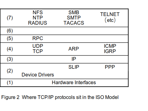
The communications hardware and the device drivers in a typical TCP/IP system map to the physical and link layers of the network. TCP/IP doesn’t worry about the exact dividing line between these layers, because the device drivers in Linux are nothing more than a data transfer agent between the hardware (which can have a surprising amount of smarts) and the caller (in this case, the Internet Protocol module).
The Address Resolution Protocol (ARP) and the Reverse Address Resolution Protocol (RARP) live at the boundary of the link and network layers. These protocols provide a way to bind physical LAN addresses (such as the Ethernet address) to IP addresses. Because this binding applies only to the local system and to directly connected LANs, these protocols live “below” the routing function. Because of its built-in routing function, IP implements the middle of the network layer.
The Internet Control Message Protocol (ICMP) and the Internet Group Message Protocol (IGMP) live at the top of the network layer. They provide information to other protocols that live at still-higher layers, and ultimately to the server (or human user).
The Transmission Control Protocol (TCP) and the User Datagram Protocol (UDP) are the two transport-layer protocols. TCP provides virtual-connection services, while UDP provides connectionless services.
In the Linux implementation of TCP/IP, all of the previously described protocols either reside in the kernel or are loaded as kernel modules. The protocols described next are implemented outside the kernel, usually either as a library routine built into the application or as a user process called a daemon.
Associated with IP in the network layer are the various routing protocols (BGP — Border Gateway Protocol, OSPF — Open Shortest Path First, and EGP — Exterior Gateway Protocol). Taken collectively, all of these protocols maintain the information in the routing table within the computer. Workstation computers rarely include these daemon; they are absolute necessary for computers located at the “network edge.”
The Secure Sockets Layer (SSL) protocol is a session layer protocol. Remote Procedure Call (RPC) is also a session-layer protocol; it rides on top of SSL, when SSL is present. In the TCP model, SSL becomes part of the top of the transport layer. RPC is treated as part of the Network File System application, because it’s one of the few applications that uses RPC.
In the TCP/IP model, the presentation layer is empty. The functions that live there in the OSI model are subsumed under the design of the applications that use TCP/IP.
Lastly, the applications that use TCP/IP — FTP, Telnet, X, mail, the World Wide Web, rlogin, finger, rsh (Remote Shell), Network Time Protocol (NTP), to mention just a few — live on the application layer.
Loading session and presentation-level protocol code into the applications has many practical advantages:
The basic TCP/IP implementation remains stable over time.
The new protocols can be implemented on top of the existing transport protocols without requiring changes in the stack.
Researchers can develop the protocols without having to hack the operating system, and their development work doesn’t affect the system when the system is used for other purposes.
An application’s code can be tweaked much more easily than an operating system can be rebuilt. (On a 300-MHz Pentium computer, it takes about 10 seconds to rebuild an experimental app and about 20 minutes to rebuild a kernel.)
Application code can be debugged with a standard debugger.
The new protocols can be implemented as library routines, which can in turn be incorporated into programs, if the programs want them. The Transport Layer Security protocol (RFC 2246, also known as the Secure Socket Layer Protocol) has been working its way into applications in exactly this way. Another protocol that has followed this path is Domain Name Service (DNS), which began as an experiment in deleting static host tables, and grew into a distributed namespace management service. Every serious Internet application uses it, but in the form of a library routine, not as a service.
An overall advantage of having presentation-level protocols in the application is that the method of allocating time to them is decided by the application, rather than being a system-tuning issue. More importantly, the application can use the library-routine interface to control the QoS parameters with respect to the presentation-level protocols far more easily than if the application had to use the application programming interface (API) to set these parameters.
In conclusion, TCP/IP has been found to fit well enough into the ISO/OSI model to allow the model to be used successfully in the development of new and improved TCP/IP protocols. The descriptions of the layers are very useful in defining the structure of networking within TCP/IP. The differences are minor (and serve as great topics for master’s theses). Most importantly, the theoretical structure of networking communications that was developed with the OSI model can be applied, with very few changes, to TCP/IP applications. This structure provides a foundation for continuing developments in TCP/IP networking, and also enables researchers to use TCP/IP as a workbench for testing and refining these developments.
Our discussion of the IP Stack system starts with layers 1 and 2, the hardware and link layer. Everything else builds on that. The actual implementation of these two layers can be a combination of circuitry, firmware, and software drivers. No matter how, the output of this part of the network scheme is a collection of 8-bit bytes, or octets, that are passed on to layer-3 software.
Figure
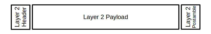
3 Overall Concept of Layer 2 data
(In Figure 3.3, we have collapsed layers 1 and 2 into a single diagram. The concept of “header” and “postamble” indicates only how the layer 2 makes the datagram payload available to the upper-layer handlers.)
One older layer-2 driver, the Serial Line Internet Protocol (SLIP), is very simple. It does one task: take data over a serial port and break it up into well-defined datagrams, the aforementioned collection of octets. There is no additional control information. The handoff to upper-layer protocols would need to be done via configuration setting. This means, for example, that DECnet and IP traffic could not be handled at the same time in a SLIP connection.
SLIP was superseded by Point-To-Point Protocol (PPP) over pure serial links. PPP is described in RFC 1661. The PPP has been extended to other layer 1 entities: point-to-point protocol over Ethernet (RFC 2516), and point-to-point protocol over ATM (RFC 2364). One big feature of PPP is that the header includes the 16-bit PPP ID field, which describes which higher-layer protocol handler should process the payload — for Internet Protocol, this ID is 0x0021.
The Ethernet format is a multi-drop system, in that multiple devices (like computers) can be connected to the same line. To support Ethernet connections, the IP stack defines the Address Resolution Protocol (ARP) that provides correspondence between IPv4 addresses to Ethernet media access control (MAC) addresses. The Ethernet frame layout contains the EtherType field to indicate where the payload should be sent — for Internet Protocol, this 16-bit ID is 0x0800.
This is by no means an exhaustive list of Layer 1 and 2 possibilities, but all of them isolate the payload, and by some mechanism indicate what layer 3 handler should process the payload.
Comments,
suggestions, and error reports are welcome.
Send them to:
ipstacks (at) satchell (dot) net
Copyright
© 2022 Stephen Satchell, Reno NV USA