Linux IP Stacks Commentary Web Edition
IPv4: Internet Protocol version 4
RFC 791 — Internet Protocol [IPv4]
RFC 1122 — Requirements for Internet Hosts -- Communication Layers Section 3.2.1
RFC 2474 — Definition of the Differentiated Services Field (DS Field) in the IPv4 and IPv6 Headers
RFC 3168 — The Addition of Explicit Congestion Notification (ECN) to IP
RFC 4774 — Specifying Alternate Semantics for the Explicit Congestion Notification (ECN) Field
RFC 4782 — Quick-Start for TCP and IP Section 3
RFC 5348 -- TCP Friendly Rate Control (TFRC): Protocol Specification
RFC 6323 -- Sender RTT Estimate Option for the Datagram Congestion Control Protocol
RFC 6679 -- Explicit Congestion Notification (ECN) for RTP over UDP
RFC 7619 — The NULL Authentication Method in the Internet Key Exchange Protocol Version 2
RFC 8311 -- Relaxing Restrictions on Explicit Congestion Notification (ECN) Experimentation
The Internet Protocol (version 4) is the “IP” in “TCP/ IP.” It performs most of the major tasks that enable the flow of information from system to system. In essence, the Internet Protocol is the “envelope” in which all user data is placed so that it can be transmitted anywhere on the Internet.
Like a paper envelope, IP has a destination address, a return address, and handling instructions aimed at the many entities that handle the data. IP even has an analog to the sorting of paper letters according to post-office boxes, so that data packets intended for TCP don’t get mixed up with letters intended for UDP, and ICMP packets are kept segregated. (These are just 3 of the types of objects that IP can handle; another 252 types are possible, 97 of which are defined in RFC 1700.)
Unlike its physical counterpart — the United States postal service — IP doesn’t believe there is any such thing as an “oversized” letter. When the amount of data to be transmitted is too large to fit into the “envelope,” IP simply breaks the data down into chunks that are small enough for the data-transmission procedures to handle.
These chunks, called fragments, can be created at any point during the transfer of data from an originating system to a destination system. When all the fragments of a data packet have arrived at the destination system, the Internet Protocol reassembles them into a single large packet, and passes this packet up to the next-higher protocol layer.
This section examines version 4 of the Internet Protocol (IPv4), which is the version that is used on the Internet today. IPv6 will be considered in another section.
In brief, the IPv4 part of TCP/IP performs the following jobs:
These tasks are closely linked with the format of Internet Protocol data packets, which are the subject of the rest of this section.
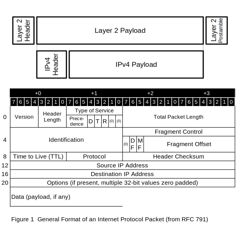
Figure 1 shows the general layout of an Internet Protocol packet. Such IP packets are transmitted via serial data-communications lines, with the 8-bit octets shown in these illustrations being forwarded in order, from left to right and from top to bottom. Although the specific transmission method for the bits in each octet is defined by the underlying hardware, standard practice calls for the least-significant bit to be transmitted first.
The following subsections describe each of the fields in the Internet Protocol packet.
The Version field (octet 0, bits 7 through 4) indicates the type of packet. For IPv4 packets, this field contains the binary value 4 (01002).
The Header Length field (octet 0, bits 3 through 0) contains the number of 32-bit words in the IP packet header. Because the minimum header size is 20 octets (that is, five 32-bit words), the minimum value of this field is 5. The only time this field has a value other than 5 is when the header contains IP options — which is a relatively rare occurrence on today’s Internet.
The Type-of-Service field (octet 1), also referred to widely in the literature as the “TOS field,” is broken up into four bitfields: the 3-bit precedence classification, the single bit delay handling flag, the single-bit throughput handling flag, and the single-bit reliability handling flag. The remaining 2 bits are reserved for future use and should be set to zero. The Type of Service field allow routers to do traffic shaping: to schedule the transport of packets in ways that improve the apparent (and actual) performance of network applications.
In the original U. S. Department of Defense (DOD) definition of TCP/IP, the contents of the type-of-service field were used to determine when certain packets should be sent ahead of other packets. RFC 795 (September 1981) describes how the information in this octet was mapped to the requirements of various datanet services that were in use at the time:
Bits 7-5 |
Meaning |
Bits 7-5 |
Meaning |
111 |
Network Control |
011 |
Flash |
110 |
Internetwork Control |
010 |
Immediate |
101 |
CRITIC/ECP |
001 |
Priority |
100 |
Flash Override |
000 |
Routine |
Bit |
Meaning when 0 |
Meaning when 1 |
4 (D) |
Normal Delay |
Low Delay |
3 (T) |
Normal Throughput |
High Throughput |
2 (R) |
Normal Reliability |
High Reliability |
In military and government networks, the precedence field is often very important. However, in the mostly civilian and commercially oriented data universe known as the Internet, this octet is largely ignored.
The Total Length field (octets 2 through 3) contains the 16-bit length (in octets) of the entire packet (that is, of the header, the IP options, and the data). This length field limits the maximum size of the packet to 65,535 octets. Most of the protocols (such as ICMP, TCP, and UDP) that live on a layer above IP restrict themselves to packets whose size fits the maximum transmission unit (MTU) that can be sent over the path between the systems. (One notable exception is the Sun Network File System, commonly known as NFS, which in many implementations uses packets that contain 8,192 data octets.)
The Identification field (octets 4 through 5) contains a 16-bit packet sequence number. When a data packet can be transmitted in its original form, with no modifications, this field is ignored. However, if a packet needs to be fragmented, the Identification field is used to identify all the resulting little pieces, so that they can be collected at the receiving end. The Identification field also allows the defragmentation algorithms at the receiving end to reassemble, in proper order, multiple fragments derived from many large packets.
The next 16 bits are used, in conjunction with the Identification field, to keep track of fragments of packets. Fragment control consists of two flags and a 13-bit offset value.
When set, the Don’t Fragment flag (octet 6, bit 6, also referred to as the “DF” flag) indicates, to any router, that the packet in question must not be fragmented. This flag also indicates that the router in question should return an ICMP packet with a type value of 3 (“destination unreachable”) and code 4 (“fragmentation needed and DF set”). This flag is used when a system needs to discover the MTU of the path to a remote computer.
In this MTU discovery procedure, the originating system sends variously sized packets, with the DF bit set, to a remote receiving system. The path traveled by these packets may go through any number of intermediate routers. When the remote system finally responds positively, the originating system can infer the size of the MTU. Knowing the MTU, the sending system can tailor its transmission packets to use the path as effectively as possible, while also preventing packets from being fragmented in-flight.
When set, the More Fragments flag (octet 6, bit 5, also known as the “MF” flag) indicates that the packet containing the set bit belongs to a given group of packet fragments. When the receiving system receives all the packet fragments in which bit 5 is set, plus one packet fragment in which bit 5 is clear, the receiving system can proceed with the reassembly of the fragments and the processing of the packet.
The Fragment offset field (octet 6, bits 5 through 0, plus octet 7) indicates the starting position of the first data octet ― that is, the first payload octet ― in this IP packet, as this location appeared in the original unfragmented packet.
To locate the starting position in the reassembled packet in which the data from this packet needs to be placed, the receiving system must obtain a value known as the octet offset. To so do, the receiving system multiplies the contents of the Fragment Offset field by 8. This algorithm implies that fragment reassembly is governed by certain rules, to wit:
For fragments other than the last fragment, the length of the data portion of the packet (that is, the payload) must be equal to a multiple of 8 octets, and the length of the data portion plus the fragment offset must not exceed the length of the original unfragmented packet.
For the last fragment, the sum total of the number of octets in the data portion, plus the fragment offset, must not exceed the length of the original unfragmented packet. Some ill-intentioned system crackers have taken advantage of lax internal programming practices in order to perpetrate buffer overrun attacks, which are launched through packets that violate this length-limitation rule.
For any fragment, the sum total of the number of octets in the data portion, plus the fragment offset, must not exceed 65,535. Because this requirement forces the IP fragment reassembly code to write to astonishing locations in memory, it has given rise to the so-called Ping of Death packet, which is another, more insidious example of a buffer overrun attack.
(Most Linux systems today run on 64-bit machines, and are 64-bit operating systems. Older Linux systems are 32-bit operating systems—ill that runs on 32-bit computers, so the bounds test, which determines whether the specified number of octets has been exceeded, can easily be performed. However, making this determination is not so easy on 16-bit machines. On these systems, programmers must be very, very careful if they don’t want to be bitten by an undetected buffer overflow.)
So, then, exactly how are packets reassembled? Well, first of all, the packet-reassembly algorithm collects the fragments, using the contents of the following four fields as a key:
After it has obtained the contents of these fields, the algorithm sorts the fragments into groups known as collections. When a collection is complete — with at least one fragment that covers each octet of the packet that is being reassembled — the original packet can be rebuilt and processed, and the fragments (which are no longer needed) can be discarded.
Strange things can happen on the Internet. Accordingly, the reassembly algorithm needs to be able to deal with fragments that are exact duplicates of packet fragments that have already been received. The reassembly algorithm may also have to deal with multiple copies of fragmented data, or with fragments that arrive in no discernible order — or even overlap each other.
Another game malicious system crackers play involves the generation of streams of bogus fragments, filled with data that differs from fragment instance to fragment instance, in an attempt to circumvent the packet-filtering rules in firewalls.
The destination system can’t reassemble an entire original packet unless all the constituent fragments are present. So, what can the reassembly algorithm do when a fragment is lost? The answer is rooted in time.
Incoming fragments must reach the reassembly algorithm within a given period of time, which may differ from system to system. Release 2.0.34 of the Linux kernel uses a deadline (known as a timeout value) of about 30 seconds. (The source code has been somewhat ambiguous about timeout values. For the moment, assume that the 30-second clock is restarted each time a fragment reaches the reassembly algorithm in the destination system.)
If one or more deadline periods have passed, such that the destination system concludes that it will probably never receive all the fragments that belong to a given packet, then the destination system will discard all the fragments that it has already received. Its next decision is whether to send an informative ICMP message (see section ICMP) back to the originating system.
If the receiving system has acquired an incoming packet’s IP header and at least the first 8 octets of the packet’s data portion, then it can generate an ICMP message to notify the originating system that a problem has occurred. If the receiving system has not acquired this minimum data, it cannot generate any ICMP messages, and the fragments in question quietly disappear into the bit-bucket.
The 8-bit Time To Live field (TTL, octet 8) is initially set to the maximum number of routers that a packet may visit. As each router forwards the packet, the value contained in the TTL field is decremented by 1. If a router finds itself about to transmit an IP packet whose TTL value is 0, the router drops the packet and generates an ICMP packet with a type value of 11 (time exceeded) and a code value of 0 (TTL equals 0 during transit).
Here, the word “time” is a misnomer, because no way exists for today’s routers to know exactly when a given packet was launched into the Internet. The initial meaning of the TTL value, which used to refer to clock time, now refers instead to the maximum number of routers through which a packet can be forwarded.
When an IP implementation fragments a packet (or fragments a packet fragment — this process can be iterative), each fragment that is generated by the router inherits the TTL value from the received packet that the router is fragmenting at that moment. For example, a system sends out a packet whose TTL value is 64. Over the course of this packet’s travels, its TTL value is decremented by intermediate routers, such that when the packet arrives at the router in question, its TTL value is (for instance) 51. In this case, the TTL value that is inserted into the fragments is 51 minus 1, or 50. Because of this inherited TTL value, each fragment has a finite “lifetime” within which it must reach the destination system. In other words, fragmentation does not extend a packet’s life expectancy.
The 8-bit protocol field (octet 9) contains the identification of the next-higher-level protocol in the data portion (that is, the payload) of the IP packet. This value may range from 0 to 252. For example, the protocol field contains the value 1 if the payload contains an ICMP packet; the value 6 if the payload contains a TCP packet; and the value 17 if the payload contains a UDP packet. RFC 1700 lists all the values that may appear in this field in the IP header. The list of protocols that Linux knows about may be found in the file /etc/protocols.
The 16-bit Header Checksum field (octets 10 and 11) contains the checksum of the entire IP header. When an IP protocol handler receives a packet from a device driver, it can use this checksum to confirm that the header has not been damaged. The algorithm for calculating this checksum consists of the one’s-complement sum of a certain number of values (usually from 10 to 30 of them), each of which contains 16 bits, with the checksum field initially set to 0.
The length of the header is obtained from the data that is being verified. Although at first glance this procedure may seem risky, closer examination of the possible error modes shows that the checksum verification will generate a true negative even if the length field itself is damaged.
The payload is not checksum-protected at this level. That task is left to the protocols (such as TCP or UDP) that process the payload.
The 32-bit source address field (octets 12 through 15) and the 32-bit destination address field (octets 16 through 19) contain the IP address of the originator of the packet and the IP address of the intended recipient of the packet, respectively.
The Options field (octets 20+) contains zero or more IP option specifications that may be present in the IP packet header, and range in length between 0 and 40 octets (ten 32-bit “words”) of additional information. There are four so-called “classes” of option specifications indicated by bits 5 and 6 of the first octet:
The packet option specifications are structured such that if the implementation of the TCP/IP stack doesn’t recognize the specification, it can successfully step past the unknown data when analyzing the packet.
Each option specification starts with a one-octet identifier, followed by data (if any) associated with the specification. If the option specification can contain additional data, it contains an 8-bit octet length fields, followed by the information associated with the specification. Each specification may start at any octet position (not necessarily on a 32-bit word boundary). Options field must be padded with end-of-list (0) codes until it reaches a word (32-bit boundary)
Figure 4 shows the format of the specifications:
None of these options are used regularly on the Internet today. Why?
Source routing is viewed as a security problem.
The Security field is useful only in military networks.
The SATNET Stream ID is useful only on SATNET.
The Internet Timestamp and Record Route functions can’t carry enough data, because the structure of the Internet virtually guarantees that your packets will pass through more than nine routers.
Table 1 lists all the types of options as of this writing.
In general, when generating two or more fragments from a packet with options, you copy some of the option specifications but not others into all the fragments. This detail, as well as the meaning of any option specification payload, can be found in the RFC document shown in the table
Some implementation will not insert no-operation (type 00000001) option specifications between two specifications. Others will add no-operation specifications to align the start of the next option at a 32-bit boundary. Best practice is to copy the no-operation specifications, ignoring the copy bit in the option specification header byte.
The payload are the octets that will be transferred to the application running on the receiving system. The payload may be empty. The upper limit for the payload depends on the IP options included in the packet; the IP header + payload should be less than or equal to the MTU for the connection — this reduces the number of packet fragments that need to be reassembled at the receiving end.
To flesh out the requirements of an Internet Protocol implementation, we must discuss RFC 1122. This document, entitled Requirements for Internet Hosts — Communication Layers, lists the “shoulds” and “musts” and “should nots” and “must nots” that are important in IP implementations.
RFC 1122 isn’t just some random programmer’s good ideas. It is a standard, as defined by the computer industry, and therefore constitutes the widely accepted “word from on high.”
At this point, some quotations are in order. Here are a few representative decrees from RFC 1122:
For incoming datagrams, the IP layer:
Verifies that the datagram is correctly formatted;
Verifies that it is destined to the local host;
Processes options;
Reassembles the datagram if necessary; and
Passes the encapsulated message to the appropriate transport-layer protocol module.
For outgoing datagrams, the IP layer:
Sets any fields not set by the transport layer;
Selects the correct first hop on the connected network (a process called “routing”, discussed in the section routing);
Fragments the datagram, if necessary and if intentional fragmentation is implemented (see Section 3.3.3); and
Passes the packet(s) to the appropriate link-layer driver.
A datagram whose version number is not 4 MUST be silently discarded. [This requirement assumes that IPv6 has not been implemented, as is the case in Linux kernel release 2.0.34.]
A host MUST verify the IP header checksum on every received datagram and silently discard every datagram that has a bad checksum.
A host MUST silently discard an incoming datagram containing an IP source address that is invalid by the rules of this section. This validation could be done in either the IP layer or by each protocol in the transport layer.
A host MUST NOT discard a datagram just because it was received with TTL less than 2.
The IP layer MUST NOT crash as the result of an option length that is outside the possible range.
The foregoing excerpts are just a few of RFC 1122’s many requirements. The requirements have been updated by a whole list of RFCs: 1349, 4379, 5884, 6093, 6298, 6633, and 6864 — and it’s a sure bet this list will be extended. (Wouldn’t it be nice if all of these host requirements were collected into a single document?)
Comments,
suggestions, and error reports are welcome.
Send them to:
ipstacks (at) satchell (dot) net
Copyright
© 2022 Stephen Satchell, Reno NV USA